Page 1 of 1
Pickup winder counter Help
Posted: Sat Oct 13, 2012 12:43 am
by Chris Mudd
Hello all,
I am either making this too complicated, or don't realize how much I don't know.
I am designing a pickup winder and am stuck at adding a way to count windings. will it work if If I add one of the counters in the link below?
Is it really that simple?
Chris
http://www.ebay.com/itm/Punch-Counter-L ... 43b3b6b000
Re: Pickup winder counter Help
Posted: Sat Oct 13, 2012 5:26 am
by Greg Robinson
Hi Chris,
That should work fine, so long as it lives up to its specs. It can count up to 1200 rpm (I wind around 800 rpm), so hopefully it won't have any bounce issues. The only thing that might be the trick would be balancing the spindle on your winder for the magnet the sensor requires. I use an optical (phototransistor) switch on mine.
Good luck.
Re: Pickup winder counter Help
Posted: Tue Oct 16, 2012 2:05 am
by David King
The 1200 cpm figure may require that the dwell time be close to 50% on and 50% off. You will need a magnet armature that goes 1/2 way around the shaft. I wind at around 1000 rpm and that can mean almost 40 minutes of winding for a pair of bass HBs. I would much rather winds faster if I could control tension accurately.
Re: Pickup winder counter Help
Posted: Sat Oct 20, 2012 12:28 pm
by Markku Nyytäjä
The counter of my power drill winder counts up to 720 RPM. No wonder I never make it home before 9 PM.

Re: Pickup winder counter Help
Posted: Mon Oct 22, 2012 2:44 pm
by David King
Optical sensors are OH SO MUCH easier to to work with than hall effect or those silly reed switches but misinformation on the web persists forever...
Re: Pickup winder counter Help
Posted: Wed Oct 24, 2012 4:20 pm
by Chris Mudd
Ok, so here goes,
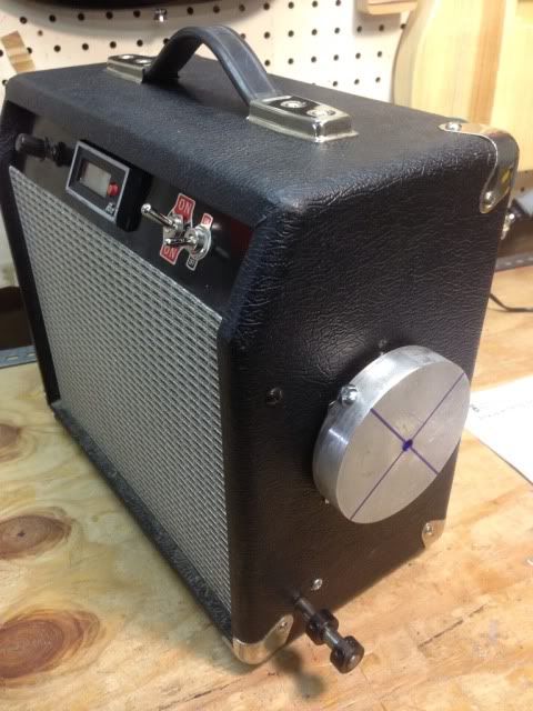
I am planning on using an optical sensor hooked up to an up/down counter with a relay. My goal is to end up with a variale speed AC motor (courtesy of an old Duracraft bandsaw)that will shut itself off at a preset amount of winds. I have been lusting after the counter that Clint Searcy uses on Youtube.
I have seen builders use a CD rotating through the center of the optical sensor to send pulses to the counter. I have noticed that the reed switch and magnetic idea could be too inaccurate.
THANKS ALL
I love this forum!!!!!!
Re: Pickup winder counter Help
Posted: Thu Jan 10, 2013 2:10 pm
by Greg Martin
david king, do you know how to set up this for a winder any links pictures or advise is welcome
Re: Pickup winder counter Help
Posted: Thu Jan 10, 2013 2:30 pm
by David King
Greg,
What sort of winder winder? What model counter?
I used a fairchild QRD 1114 with a reflective disk
Here's a link to the datasheet
http://www.fairchildsemi.com/ds/QR/QRD1114.pdf
There are several recent threads around here and hundreds of threads over on the pickup winder's section at the music-electronics forum.
Re: Pickup winder counter Help
Posted: Fri Jan 11, 2013 3:36 pm
by Patrick Macy
I went with a Hall Effect Sensor. because the optical ones were giving some guys fits with ambient light.
This thing works great.

Re: Pickup winder counter Help
Posted: Fri Jan 11, 2013 4:04 pm
by David King
Well the hall effect sensors were giving some folks fits with insufficient dwell time. It's going to depend on the counter/totalizer that you choose.
IR sensors should't have any trouble with ambient light as they are reading a direct reflection at very close quarters. I used aluminum foil tape for the reflective surface and silicon carbide sandpaper for the non-reflective sections of my disc.
Re: Pickup winder counter Help
Posted: Tue Jan 15, 2013 1:47 pm
by Greg Robinson
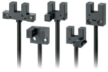
There are many optical sensors designed to be used in daylight conditions, they usually have filters for visible light - the better ones only pass a narrow band of ir. If you're using the most common package type:
link, then just making sure your interrupter fills as much of the gap between the ir led and the sensor as possible while still turning freely should shield it from most ambient sources.
Re: Pickup winder counter Help
Posted: Tue Jan 29, 2013 9:41 pm
by David Ackley
I recently decided to upgrade to a counter rather than tediously measuring resistance. I bought a magnetic reed switch and tried hooking it up to both a pedometer and a calculator. Neither was satisfactory beyond very slow speeds. I saw a reference for a DIY up/down counter and am pleased with the results. It has a large well-lit display and includes a chip that takes care of the bounce problem. I expected a little more speed, since it seems to max out at 700 rpm, but find that is a very reasonable speed for me. If anyone is interested, it is DIY kit 129 found at
http://www.electronickits.com/ among other places.
Re: Pickup winder counter Help
Posted: Wed Jan 30, 2013 2:27 am
by David King
Here's the link to the 4 digit programmable up/down counter.
http://www.electronickits.com/kit/compl ... ck1612.htm
That place has a LOT of kits, the most I've ever seen in one place.
David,
What are you using as your trigger? It may be a dwell time issue as opposed to a count speed problem. If you can lengthen the "on" time of the trigger to 50% of total time per revolution you might gain some significant speed.
Re: Pickup winder counter Help
Posted: Wed Jan 30, 2013 5:15 pm
by David Ackley
Hi David,
I'm not sure what you mean by "trigger". I have a magnet on the back of the disk that holds the bobbin, and then have a magnetic reed switch to register when the magnet passes. I have hooked these up to the "count" pins on the counter. In theory, the information says that the counter should register 30 - 35 counts per second, whereas I seem to be getting around 11 (or 22 for every high/low - low/high transition?). I would love to add refinements to this great counter. Perhaps a better reed switch or an optical switch?
Re: Pickup winder counter Help
Posted: Wed Jan 30, 2013 10:17 pm
by David King
David.
The reed switch is your trigger. Every time the magnet passes, the switch closes, and sends a square wave pulse to the counter.
Can you guestimate for how long the magnet is keeping the the reed switch closed at 700 rpm?
If the pulse[width] is too short then the counter can't see it. You need to find a way to make the pulses longer. In technobable this is called the "dutycycle" or percentage of the time that the pulse is "on" vs the time it's "off". You want to achieve a 50% dutycycle for highest reliability at maximum speed.
In practical terms what this means is you need to add a string of magnets to keep the reed switch closed for half way around the disk. This may prove impractical but that's the shortfall of reed switches. I don't know who keeps recommending them but they are not particularly suitable to this job.
Re: Pickup winder counter Help
Posted: Thu Jan 31, 2013 12:37 am
by Greg Robinson
Adding a Schmitt trigger to reduce switch bounce may help, but an optical sensor would be more reliable and be capable of higher speeds, although you will still likely need a debounce circuit.
Re: Pickup winder counter Help
Posted: Thu Jan 31, 2013 1:01 am
by David King
Quoting from the PDF doc for the counter:
Each input to the IC is connected via an RC network. This
RC network provides some protection against high
frequency noise. For the values used the time constant is
approx. 20uS. Shorter duration pulses will not get through.
I wonder if they meant milliseconds instead microseconds...
Re: Pickup winder counter Help
Posted: Thu Jan 31, 2013 2:10 am
by David Ackley
The counter includes a debounce circuit which is 15 msec, so hopefully this is not a factor. I may try a longer magnet, or change the magnet orientation to see if that makes a difference. I also might see if I can find a different reed switch that is made more for fast operations. And I also will probably try out an optical sensor since I am getting into this now. I have seen some reflective sensors on the web, but know nothing about the circuitry that would be needed to power it - is this pretty straightforward? Thanks for the input.